Sweet. I like the plug index. Very nice detail that is often overlooked.Today i got the new Manley valves installed in the heads. They fit, and with a minimal grind on the valves, they sit nice and deep in the seats. I checked the intake valves clearance to the deck of the heads with my piece of aluminum flat bar, and it looks like about .105". With the factory valves, the clearance measured about .068"... so i've picked up .037"! Going back to my measurements from a previous post where i found .028" PTV clearance on the intake valves at 8 degrees ATDC, i'm hoping that measurement will now be about .065", which would be within spec.
Since the block and heads have been sitting (even though covered in plastic) for a couple months, i'm going to remove, clean and oil the pistons and bores tomorrow before i reassemble and degree the cams... hopefully for the final time!
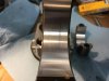
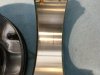
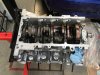
Here are a couple photos of the new valves installed, and the intake valve to head deck clearance (valve droop).
Fingers crossed, eyes crossed... ...regards, kevin
-
Hello there guest and Welcome to Modular Fox Mustangs home of the 2V, 3V, 4V, Coyote Modular Mustang Conversion Information Website!
To gain full access you must Register. Registration is free and it takes only a few moments to complete.
Already a member? Login here then!
You are using an out of date browser. It may not display this or other websites correctly.
You should upgrade or use an alternative browser.
You should upgrade or use an alternative browser.
Teksid 2V Tech Article (Must Read)
- Thread starter ModFoxMustangs
- Start date
I'd love to take credit for the plug index, but the truth is Ford made me look good  .
.
I've been (slowly) taking out the pistons and cleaning/oiling them and the cylinders. As i noted
before, this project has been sitting for a couple months while waiting for valves, so i wanted to
make sure i get rid of the dust and spiders (ok, slight exaggeration) before i close it up. When
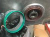
i took apart the rods/caps, i noticed a hint of scoring on #7 rod bearings. It's not deep, in fact
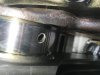
i can barely notice it when i run a fingernail across it, but still... Here are a couple photos of the
bearings and one of the rod journal on the crank. The oil feed hole has been roughly countersunk a bit,
and it looks like there might be a tiny burr on it, causing the bearing marks? Is this serious? Should
i take a chance on using emery cloth or a fine file (with the shop vac right there) on the edge of
the oil hole, or would this be foolish?
More bad $#%*! language in the shop today... ...regards, kevin
ps. these are new bearings, and the scoring is from me turning the crank by hand while trying to
degree the cams a couple months ago. ARP cap fasteners, torqued to 45 ft/lbs.
. I've been (slowly) taking out the pistons and cleaning/oiling them and the cylinders. As i noted
before, this project has been sitting for a couple months while waiting for valves, so i wanted to
make sure i get rid of the dust and spiders (ok, slight exaggeration) before i close it up. When
i took apart the rods/caps, i noticed a hint of scoring on #7 rod bearings. It's not deep, in fact
i can barely notice it when i run a fingernail across it, but still... Here are a couple photos of the
bearings and one of the rod journal on the crank. The oil feed hole has been roughly countersunk a bit,
and it looks like there might be a tiny burr on it, causing the bearing marks? Is this serious? Should
i take a chance on using emery cloth or a fine file (with the shop vac right there) on the edge of
the oil hole, or would this be foolish?
More bad $#%*! language in the shop today... ...regards, kevin
ps. these are new bearings, and the scoring is from me turning the crank by hand while trying to
degree the cams a couple months ago. ARP cap fasteners, torqued to 45 ft/lbs.
Attachments
Given what you have planned and the amount of time and money you have invested, you absolutely want to clean that burr up. It doesn't appear the bearing is damaged through the beak-in coat, but hard to tell through the photos. Just be sure that you are careful and use an appropriately very fine abrasive. I tend to use a Dremel on things like that. The shop vac will help, but be sure to wipe it down with a lent free oil cloth to ensure you pick up all the tiny pieces of debris. There are a lot of techniques out there to isolate and clean stuff like that. Some of it is science and some is more art. Everyone has their preferred methods based on how they learned (including me).
This is one of those low points in a project. I took the bearings to the shop that did the machine work and the owner said it should be fine. I sure don't like the look of the oil hole, but he said the journal has been polished and that shallow scoring on the bearings is just cosmetic. As i mentioned, i can barely feel it with a fingernail... Looks like a potential hot spot to me, but i'm certainly no expert. Gawd, i'd hate it if that bearing spins or burns!
Are the bevelled edges of the oil holes in the journals usually smoothed out after chamfering them and before polishing? The more i learn about this project, the more i realise i have a lot to learn. ...regards, kevin
Are the bevelled edges of the oil holes in the journals usually smoothed out after chamfering them and before polishing? The more i learn about this project, the more i realise i have a lot to learn. ...regards, kevin
This is one of those low points in a project. I took the bearings to the shop that did the machine work and the owner said it should be fine. I sure don't like the look of the oil hole, but he said the journal has been polished and that shallow scoring on the bearings is just cosmetic. As i mentioned, i can barely feel it with a fingernail... Looks like a potential hot spot to me, but i'm certainly no expert. Gawd, i'd hate it if that bearing spins or burns!
Are the bevelled edges of the oil holes in the journals usually smoothed out after chamfering them and before polishing? The more i learn about this project, the more i realise i have a lot to learn. ...regards, kevin
If it were me, i would ask them if they would back up their claim by guaranteeing their work if the bearing does fail down the road. Put their money where their mouth is, so to speak.
"Are the beveled edges of the oil holes in the journals usually smoothed out after chamfering them and before polishing?"
My machine guy always beveled edges and completed all other machine work before polishing, so that the final polish and clean was what the customer (me) received. I don't remember an oil bevel looking rough like that. If it truly is cosmetic, the small scoring will just hold oil. If not... I can't honestly say without putting hands on it, but I would think it would be easy to clean up. Can you feel the burr on the journal? You could run a piece of cheap pantyhose across it to see if it snags. It is a bit old school, but it worked in the 70's.
One of my issues is that the striations all run on the same axis, which tells me he used a grinding disc type tool to create the bevel instead of a high speed rotary tool. That would really not be my preference, as it creates unnecessary inconsistencies in the work.
Last edited:
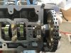
I agree, the chamfer is messy. I went back to the shop again today to look at other cranks for comparison. The owner reassured me again that there's no fatal flaw, but he did look closely at the bearings before saying so. I ran a strip of paper across the oil hole, and nothing snagged. I also had a real close look and feel at that journal. If i was the one doing that chamfer, i would've gone full OCD on it, but i tend to be meticulous to a fault sometimes So, today i torqued all the rod caps (with lots of assembly lube on the bearing surfaces, and clean and dry on the back of the bearings), cleaned the pistons and cylinders and oiled them, and installed the windage tray. For the record, i used ARP moly lube on the cap fasteners and torqued them gradually to 45 foot pounds. The windage tray fasteners (ARP) i used threadlock and torqued them to 32 foot pounds. I had to McGuyver the oil pickup tube anchor to clear the windage tray and sit deep in the pan. Finally, i put the head gaskets on (correctly this time) and set the heads in place. Tomorrow i'll find out if the new valves will give me the clearance i need.
I appreciate your input, Bill. I'm not real happy with the crank machining, but the machinist says it's fine. If rod #7 has issues, he's going to make it right.
You learn something every day, whether you want to or not. ...regards, kevin
So, today i torqued all the rod caps (with lots of assembly lube on the bearing surfaces, and clean and dry on the back of the bearings), cleaned the pistons and cylinders and oiled them, and installed the windage tray. For the record, i used ARP moly lube on the cap fasteners and torqued them gradually to 45 foot pounds. The windage tray fasteners (ARP) i used threadlock and torqued them to 32 foot pounds. I had to McGuyver the oil pickup tube anchor to clear the windage tray and sit deep in the pan. Finally, i put the head gaskets on (correctly this time) and set the heads in place. Tomorrow i'll find out if the new valves will give me the clearance i need.I appreciate your input, Bill. I'm not real happy with the crank machining, but the machinist says it's fine. If rod #7 has issues, he's going to make it right.
You learn something every day, whether you want to or not. ...regards, kevin
Attachments
The pickup tube adapter looks nice. It looks like the one that came on some mid-90s Ford F150s. I have used similar pieces, particularly for deeper sump or asymmetric (non-centered) sump applications.
I've been away for a bit, so i'm picking up where i left off. The new valves gave me some extra PTV clearance, so i'm hoping...
I found that the left bank was very close to what the cam card specified ( intake valve open .050" at 4 degrees before TDC, and centerline at 109). Next, PTV clearance was .065" at 8 degrees after TDC, which is the closest it gets. So far, so good...
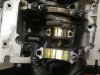
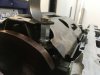
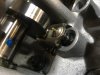
On to the right bank. I got .050 on the intake valve at 6.5 degrees before TDC, and the cam card calls for 4 degrees. I have adjustable crank gears, so i took out 2 degrees for 104.5, which put the input centerline at 109.5 (cam card says 109) after TDC. Close enough. Now, on to PTV... which is where it gets murky. I was able to use a big screwdriver to lift the cam follower until the valve met the piston on cylinder #6 on the left bank, but on cylinder #1 on the right bank, lifting the cam follower pops it right off the lash adjuster (i'm using an adjustable one for degreeing). I tried putting a pin in the lash adjuster, which keeps the follower in place, but it still lifts off the lash adjuster... messing up my measurement. No amount of careful lifting and bad language will keep the follower from popping off. I've attached a couple photos to illustrate.
Question: short of taking off the head (i've already torqued it) and using the modeling clay again, is there an easy way (or a trick i'm not using) to check PTV clearance?
...regards, kevin
Update: by wedging a small screwdriver in the valve spring retainer and against the back of the cam follower, i was able to keep the follower aligned (ok, pretty close) enough to measure .053" PTV clearance at 4 degrees after TDC (this is the closest it got). I'm going to settle for that. Comp says .060" is ideal but .050" will work on this engine.
I found that the left bank was very close to what the cam card specified ( intake valve open .050" at 4 degrees before TDC, and centerline at 109). Next, PTV clearance was .065" at 8 degrees after TDC, which is the closest it gets. So far, so good...
On to the right bank. I got .050 on the intake valve at 6.5 degrees before TDC, and the cam card calls for 4 degrees. I have adjustable crank gears, so i took out 2 degrees for 104.5, which put the input centerline at 109.5 (cam card says 109) after TDC. Close enough. Now, on to PTV... which is where it gets murky. I was able to use a big screwdriver to lift the cam follower until the valve met the piston on cylinder #6 on the left bank, but on cylinder #1 on the right bank, lifting the cam follower pops it right off the lash adjuster (i'm using an adjustable one for degreeing). I tried putting a pin in the lash adjuster, which keeps the follower in place, but it still lifts off the lash adjuster... messing up my measurement. No amount of careful lifting and bad language will keep the follower from popping off. I've attached a couple photos to illustrate.
Question: short of taking off the head (i've already torqued it) and using the modeling clay again, is there an easy way (or a trick i'm not using) to check PTV clearance?
...regards, kevin
Update: by wedging a small screwdriver in the valve spring retainer and against the back of the cam follower, i was able to keep the follower aligned (ok, pretty close) enough to measure .053" PTV clearance at 4 degrees after TDC (this is the closest it got). I'm going to settle for that. Comp says .060" is ideal but .050" will work on this engine.
Attachments
Last edited:
You are already past my depth. For assemblies that were in question, I've always done the fly cut as a long term insurance policy against cam or component changes that might be made in the future.
Modular Head Shop Checking Springs and Retainers for 7mm Valve Stems
Modular Head Shop Aluminum Checking Retainers and Springs for Cam Degree. Fits 7mm Stem, 7 Degree Locks.
www.modularheadshop.com
I thought Moroso used to make these, but could not locate.
These are very light springs for checking for PTV contact without bending a valve. Not strong enough to spit out a follower.
SWEET! I will be doing this build again in the next year and this would make that job so much easier.These are available in 6mm valve stem, and 7mm valve stem sizes.Modular Head Shop Checking Springs and Retainers for 7mm Valve Stems
Modular Head Shop Aluminum Checking Retainers and Springs for Cam Degree. Fits 7mm Stem, 7 Degree Locks.www.modularheadshop.com
I thought Moroso used to make these, but could not locate.
These are very light springs for checking for PTV contact without bending a valve. Not strong enough to spit out a follower.
SWEET! I will be doing this build again in the next year and this would make that job so much easier.
I've degreed a lot of modular cams over the years lol. I'm just glad they are still available.
Thanks for the tip, i actually do have checking springs that came with the Trick Flow degreeing kit, but the valves are already installed with the heavier springs i got... so, no easy PTV checking for me. I only had trouble with cylinder #1 (i checked 6 on the other bank), but i was able to McGuyver things enough to get .053" intake valve clearance on the dial indicator, a good improvement over the factory valves.
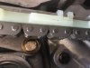
I've been hanging out with grandboys for the past few days, should be back in the shop tomorrow. I used a piece of 2-1/2" exhaust pipe to tap in the front crank seal, so i'm going to pull the keeper pins out of the timing tensioners and close up the front timing cover tomorrow. Locktite on all bolts. I'm painting the valve covers and putting those on next. The rear main seal and cover are on, oil pan is on. Something that i've seen very little about in the videos i've watched is the reluctor on the crank shaft. It sits right in front of the crank gears, and works with the crank position sensor on the right side of the timing cover. The cam gear sensor goes in the left top of the timing cover, and senses a timing mass on the cam gear.
I'll have more photos tomorrow, including moving the heat sensor to the location by the thermostat. Then i just need to install a proper oil filter relocation kit and engine oil cooler inside the left front fender. ...regards, kevin
Attachments
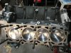
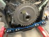
Here are a couple photos of timing components. Note the sculpting of the bolt head holding the drivers' side timing guide. It was a bit too close to the chain. A close shot of the reluctor, and also the RTV silicone where the pan meets the block. I applied more silicone to the area where the heads meet the block as well (as mentioned by Bill in post #69, and Massacre in post #73, thanks guys), just before i mounted the timing cover.
Amazingly, the stack of parts is dwindling! ...regards, kevin
Amazingly, the stack of parts is dwindling! ...regards, kevin
Attachments
Looks awesome. I don't recall ever having a guide bolt that close. Your solution looks perfect.
You're very kind, Bill
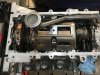
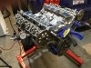
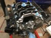
Today i emptied another couple boxes. I applied some RTV silicone to the join between the heads and the timing cover, just to make sure the valve covers seal. I retorqued the head studs (not really any movement) and gooped some assembly lube on the cam lobes. Threadlock on everything inside the covers. I also installed the heater core feed tube (not a perfect fit, but it's ok) with new O-rings. Here's what it looks like after i installed the water pump and cam/crank sensors. I'm starting to get nervous because i might actually be ready do the swap some day soon...
...regards, kevin
Attachments
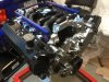
I'm going to sell the old engine in running condition, so i installed new 24lb Ford injectors (the factory injectors are 21 lb) and fuel rails. If (i hope) this Teksid 2v puts out 300hp at the wheels, the factory injectors would have been close to the max duty cycle, and i've heard a lean A/F ratio can be bad . Here's what it looks like today with injectors, rails and the new harmonic balancer. ...regards, kevin
. Here's what it looks like today with injectors, rails and the new harmonic balancer. ...regards, kevinAttachments
Any news? I've been down with the COVID and holidays, so I thought I'd check in.I'm going to sell the old engine in running condition, so i installed new 24lb Ford injectors (the factory injectors are 21 lb) and fuel rails. If (i hope) this Teksid 2v puts out 300hp at the wheels, the factory injectors would have been close to the max duty cycle, and i've heard a lean A/F ratio can be bad